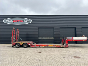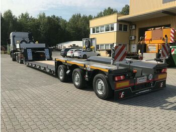
Semi-remorque surbaissé neuf Faymonville 3-Achs-Tiefbett mit Pendelachsen
Publié: 1an(s) 5mois


Publié: 1an(s) 5mois
Crédit-bail
Disponible sur demande
Avez-vous besoin d'expédition?
Obtenir un devis d'expédition
Gooseneck, rigid, in central tube design:
Gooseneck in SNT design to optimize the loading area length, length 3.800 mm
Gooseneck can be raised, lowered and detached hydraulically
For Trucks: 6 x 4, 8 x 4 (or 6 x 4 with 1-axle dolly 235 / 75-17.5)
Low deck:
Low deck designed as an extendable vessel bridge "SUPER LOW", design, length approx. 7.500 mm with mechanical locking
The supply lines are protected in the pull-out brackets and automatically adapt to the length of the low bed
Technical note: The extensibility of the loading area has been extended by approx. 300 mm, this is only used to transport "SELF-SUPPORTING LOAD" (container)
Rear chassis:
Rear chassis with closed outer frame
Covered with checker plate
Continuous prism excavator trough (approx. 1.450 x 900 x 505 mm), open at the rear
"PENDEL-AXLE", all axles hydromechanically steered
Hose rupture valve on the axle compensation cylinder with automatic RESET function
Hydraulic cylinder with stopcocks and linchpin for securing in the raised position
Technical axle load: 12.000 kg
Hydraulic axle compensation
Axis tool
Braking system:
WABCO EBS brake system in accordance with EU regulations
Tyres:
245/ 70 R 17.5
Painting:
6-component finishing:
Complete steel construction shot-peened after welding
One layer of zinc-based base paint, one layer of adhesive primer
Final painting of axes 2 layers of 2-component paint (acrylic) painted in one color in gray, then sealing of the cavities with special wax
Rims in silver
Trailer: RAL 5010 gentian blue
Metallization:
Part of HRM metallization (High Resistance Metallization)
The entire steel construction is shot-peened, then the defined visible surfaces are hot-finished with ZINACOR 850 (zinc 85% -alu15%).
Steel construction:
Steel construction made from high-strength fine-grained steels
Steel qualities:
S355J2 + N / S355MC (yield point 355MPa)
S690QL / S700MC (yield point 690MPa)
Certified welder according to DIN-EN 287-1
MAG welding process according to EN ISO 4063
Shielding gas M21 according to EN ISO 14175
Lighting:
24 volt lighting system in "ASPÖCK-NORDIK full LED"
Design in accordance with EU regulations. ASS3
Additional equipment:
Front wall made of steel, pluggable, approx. 400 mm high
1 pair of pluggable aluminum drop sides on the gooseneck, approx. 400 mm high, in an anodized design
a pluggable aluminum back panel on the gooseneck, approx. 400 mm high, anodized
External support from the gooseneck with mounting holes for screwable lashing rings
The first hole approx. 200 mm from the front, then approx. Every 400 mm
2 pairs of screwable lashing rings included (5.000 daN)
Checkered plate covering over the gooseneck
4 drag shoes with bracket
Illumination of the controls on the gooseneck
Air connection on the gooseneck
Gooseneck with 2 plug-in handrails to the loading area in the area of the folding steps for climbing the gooseneck
1 lashing ring on the left and right on the rear bevel of the gooseneck (LC 6.000 daN)
Connection strip for supply lines to the Truck, attached at the height of the outer frame profile
Hydraulic support traverse to support the gooseneck on the truck unit (or dolly)
Gooseneck in the upper rear area closed with a removable cover
Hydraulic connections from the gooseneck to the low bed with multi-coupling
One locking point approx. Every 500 mm on the extension
1 pair of steel ramps with climbing rails to bridge the hooks of the low bed with fastening bolts
Fastening options at the rear between the external beams of the gooseneck for the low bed ramps
1 lashing ring on the left and right on the front cross member (LC 10.000 daN)
Preparation on the external beams for the removable loading floor
Lashing rings with retaining springs every approx. 1.200 – 1.300 mm on the outside of the inner beams of the loading area
Lashing rings with retaining springs every approx. 1.200 – 1.300 mm on the outside of the external beams of the loading area (LC 10.000 daN)
Recesses above the lashing rings on the top strap of the outer beam
7 pairs of threaded blocks between the lashing rings under the top strap on the outer beam for the assembly of screwable RUD rings VLBG-4
2 pairs of RUD rings VLBG-4 M24 (LC 8000 daN)
Foldable extensions, by approx. 230 mm per side
6 pairs of stanchion pockets, outside on the outer beams of the low bed for stanchions approx. 100 x 50 mm
Preparations for screwable container brackets with safety bolts on the external beams
Boreholes are provided on the external supports to accommodate the holder for 1 x 20` or 1 x 40` container
Mechanical bolt-plate coupling from the low bed to the chassis, for changing the loading area or installing extension beams.
With electro-pneumatic-hydraulic couplings
1 hanging lashing ring on the outside left and right on the rear cross member (LC 10.000 daN)
The outer beams of the low bed are provided with a coated layer of sand to prevent them from slipping
Attachment bar at the front of the rear undercarriage to the low bed for loose docking ramps
2 pairs of stanchion pockets embedded in the outer frame of the rear chassis, for stanchions approx. 100 x 50 mm
1 pair of lashing rings (LC 16.000 daN) in the excavator cavity of the end chassis, in the area of the 2nd axle
1 pair of lashing rings (LC 10.000 daN) on the outside of the rear cross connection in front of the end undercarriage
When attaching a container fastening, the lashing ring must be folded up
4 pairs of lashing rings hanging in the outer frame of the rear chassis (LC 10.000 daN)
1 pair of lashing rings lying at the front in the excavator cavity of the rear chassis (LC 16.000 daN)
1 pair of lashing rings lying behind in the excavator cavity of the rear chassis (LC 10.000 daN)
Rear chassis with beveled corners at the rear
Suspension bar for loose aluminum docking ramps on the vehicle's final traverse
Insertion options at the front and rear in the arm recess of the rear chassis including a plate
Mud flaps across the entire width of the final cross member
Bracket for warning light on the vehicle's final traverse
Electro-hydraulic unit approx. 3 kW for operating the hydraulic processes except for the hydraulic cable winch
Round NATO socket on the connection strip at the front
Two 7-pin sockets on the connection strip at the front
1x NATO black 24N connection according to ISO 1185
1x NATO white 24S connection according to ISO 3731
Holder for the warning signs on the left and right, including a 7-pin socket, under the gooseneck and in front of the first axle and on the rear of the chassis
A 7-pin socket on the end traverse
Central lubrication system
Removable loading floor with approx. 30 mm thick hardwood flooring, insertable between the external beams in three elements
Axle load manometer mounted on the left
4 warning signs approx. 423 x 423 mm extendable by approx. 1.000 mm
Bracket for warning light
Yellow reflective tape on the outside along the entire length of the trailer in accordance with EU guidelines
Yellow reflective tape at the back across the entire width of the trailer in accordance with EU guidelines
EU reflector on the final cross member of the vehicle
Radio remote control for steering
An additional 15-pin socket on the connection strip at the front in accordance with ISO 12098
Cette offre est uniquement à titre informatif. Veuillez confirmer les détails directement auprès du vendeur.
Avez-vous besoin d'expédition?
Obtenir un devis d'expédition
Crédit-bail
Disponible sur demande Avez-vous besoin d'expédition?
Obtenir un devis d'expédition
Cette offre est uniquement à titre informatif. Veuillez confirmer les détails directement auprès du vendeur.
Avez-vous besoin d'expédition?
Obtenir un devis d'expédition